From a CAD model to a casting defect prediction, step by step.
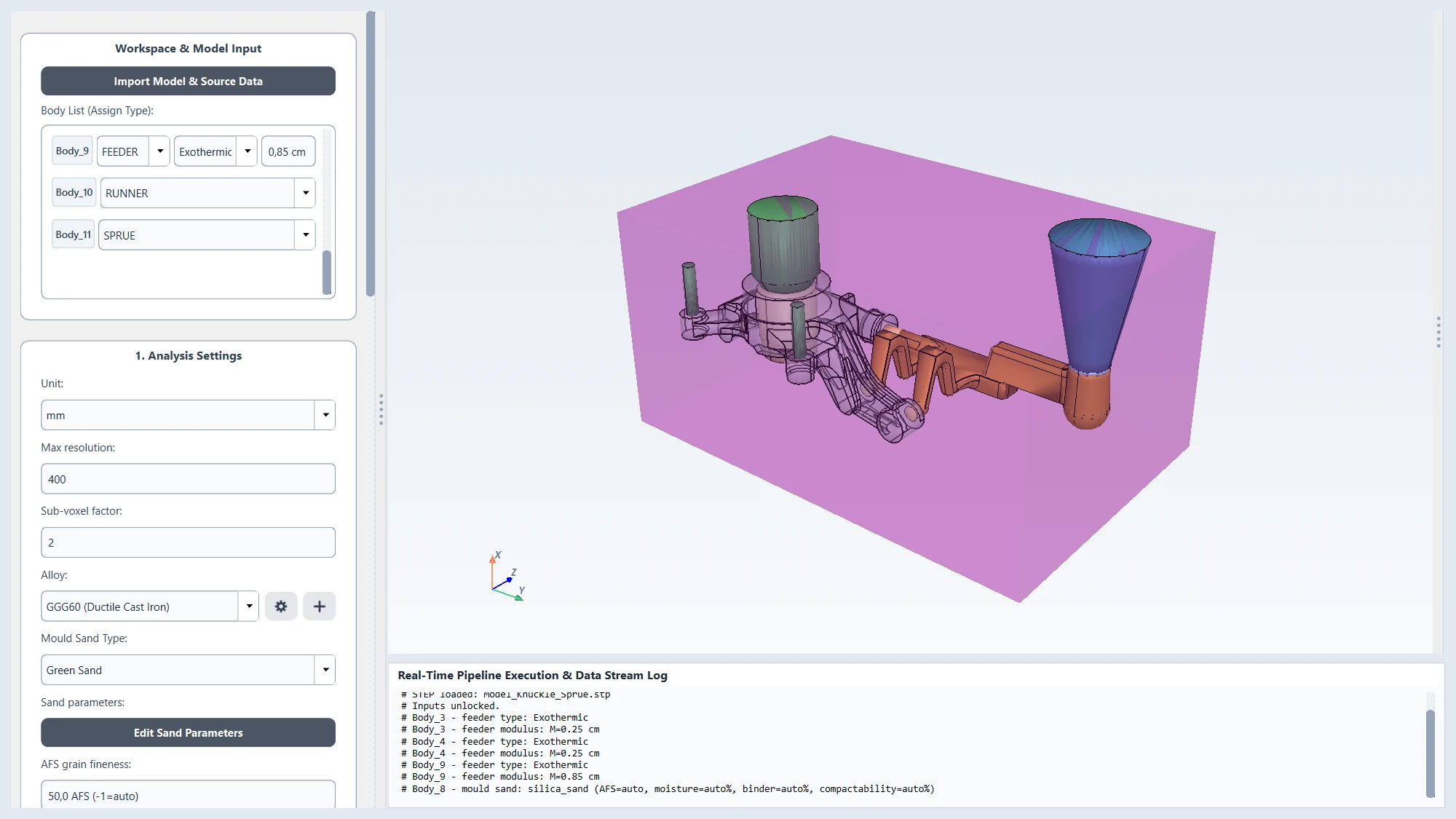
This guide walks you through one complete analysis using the sample part that ships with the program. You do not need any simulation experience. Follow the numbered steps; every picture shows exactly where to click (red frame and number).
What JoseCast Analyzer does: You give it the 3D model of your casting with its gating and feeding system. It simulates how the metal fills the sand mould and how it solidifies, then shows you where defects such as shrinkage porosity, trapped air or cold shuts are likely to appear — before you make the pattern.
Contents
- Before you start
- The screen at a glance
- Your first analysis (sample part)
- Reading the results
- Saving and opening results
- Long runs: closing the program while it calculates
- Preparing your own model
- Scope and limits
- Quick troubleshooting
1. Before you start
Computer requirements
| Minimum | |
|---|---|
| Operating system | Windows 10 (version 1809 or newer) or Windows 11, 64-bit |
| Processor | A processor with AVX2 support (almost every Intel/AMD processor made after 2015) |
| Graphics | Any graphics card or integrated graphics with OpenGL support |
| Disk | A few GB of free space for each analysis while it runs |
Install the program with the setup file (or from Microsoft Store) and start JoseCast Analyzer from the Start menu.
Sample parts. The installation folder contains a folder called Sample Parts. This guide uses Model_Knuckle_Sprue.stp — a steering-knuckle casting with its complete gating and feeding system.
How long does it take? Preparing the model takes a few minutes. The calculation itself depends on the part size and the resolution: a real part like the sample can take several hours. This is normal — the program solves the real physics of filling and solidification. You can close the window while it runs (see section 6).
2. The screen at a glance
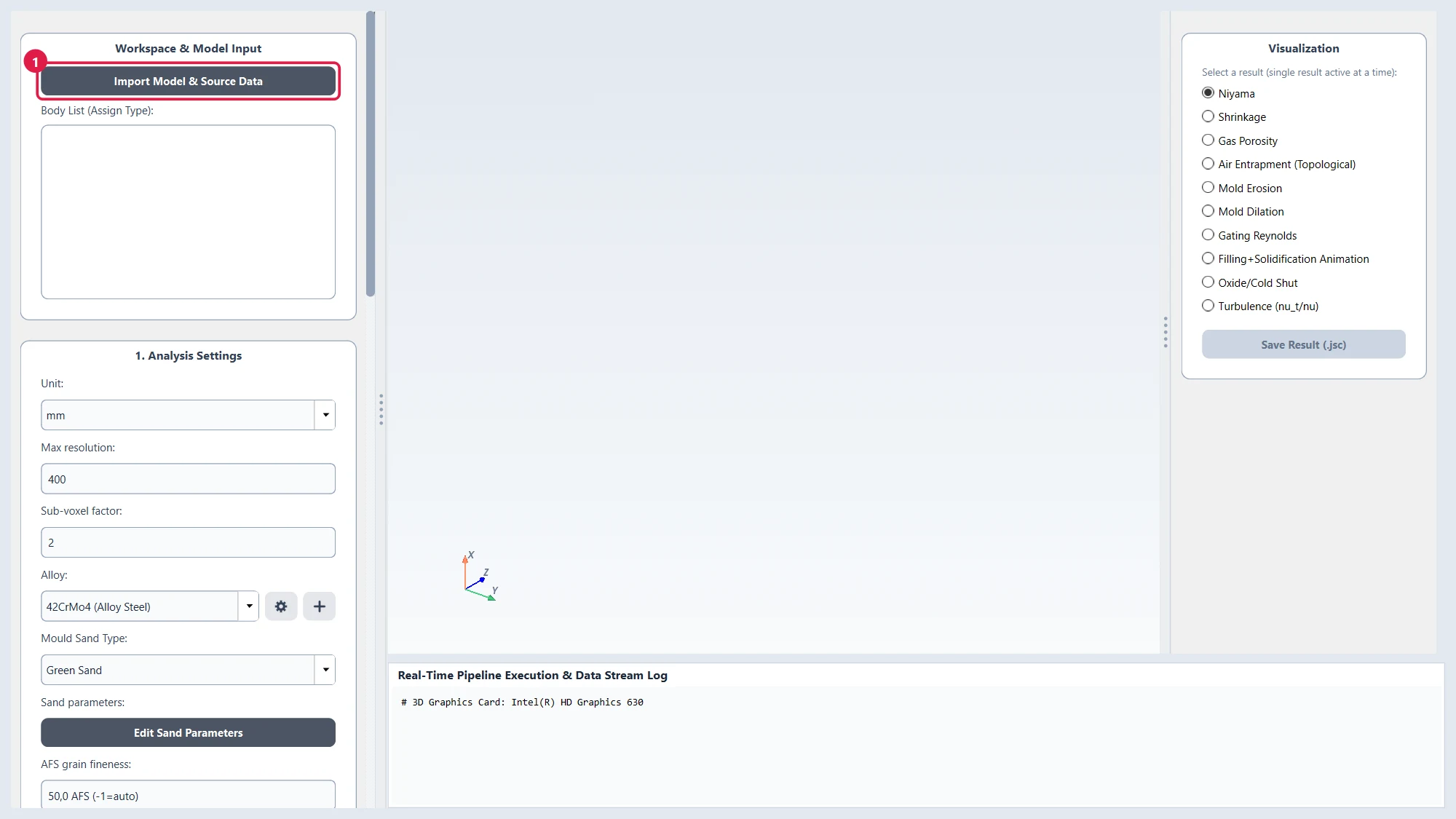
- Left panel — everything you set, from top to bottom in the order you need it: model and body types, analysis settings, casting parameters, gravity direction, and the Motor section with the action buttons.
- Centre — the 3D view. Rotate with the left mouse button, move with the middle button, zoom with the mouse wheel.
- Right panel — the list of results. It becomes active after an analysis.
- Bottom — the log. It tells you what the program is doing and warns you if something needs attention.
Tip: the left panel is long — scroll it down to reach sections 2, 3 and 4.
3. Your first analysis (sample part)
The whole workflow is always the same 8 steps:
Import → Assign body types → Choose alloy and sand → Casting parameters → Gravity → Mould box → Voxelize → Calculate
Step 1 — Import the model
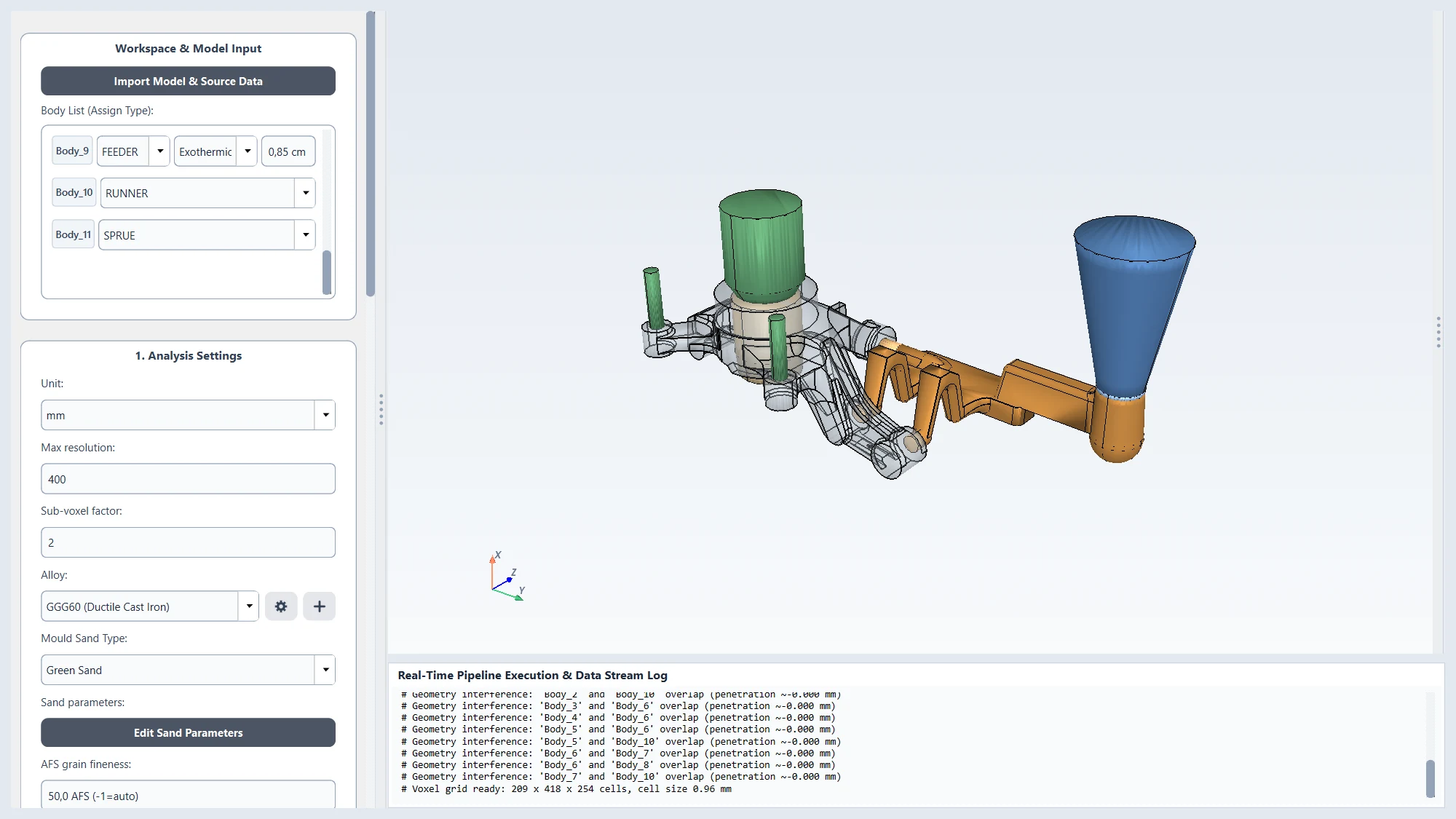
Click Import Model & Source Data (1) and choose Sample Parts\Model_Knuckle_Sprue.stp.
The model appears in the 3D view and each solid body of the file is listed under Body List (2). The sample has 11 bodies (Body_1 … Body_11). At first every body is marked PART.
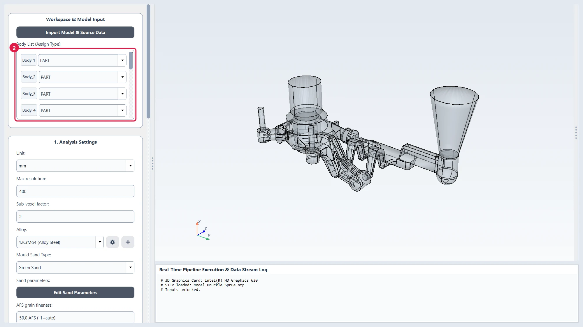
Accepted file: STEP (.stp/.step). Every component (part, feeders, runners, sprue …) must be a separate solid body in the file.
Step 2 — Tell the program what each body is
The program needs to know which body is the casting and which bodies are the gating and feeding system. Open the drop-down list next to each body name (1) and choose its type.
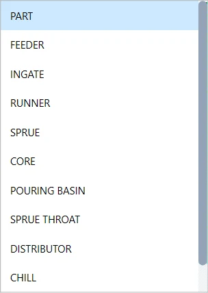
Body types in plain words
| Type | What it is |
|---|---|
| PART | The casting itself — the piece you want to produce. |
| FEEDER | A riser. A metal reservoir that feeds the part while it shrinks. |
| SPRUE | The vertical channel the metal is poured into. |
| SPRUE THROAT | The narrow bottom end of the sprue. |
| POURING BASIN | The cup on top of the sprue where the ladle pours. |
| RUNNER | The horizontal channel that carries metal to the gates. |
| DISTRIBUTOR | A runner branch that divides the flow. |
| INGATE | The short channel where the metal enters the part. |
| CORE | A sand core that forms an inner cavity (no metal inside). |
| CHILL | A metal insert placed in the mould to cool a region faster. |
To find out which body is which, click a body in the list — it is highlighted in the 3D view.
For the sample part, set:
| Body | Type |
|---|---|
| Body_1 | SPRUE THROAT |
| Body_2, Body_5, Body_7 | INGATE |
| Body_3, Body_4, Body_9 | FEEDER |
| Body_6 | PART |
| Body_8 | CORE |
| Body_10 | RUNNER |
| Body_11 | SPRUE |
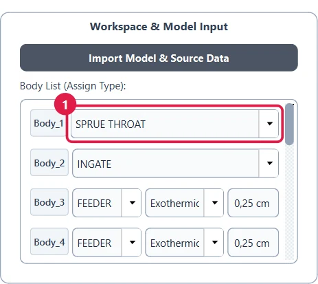
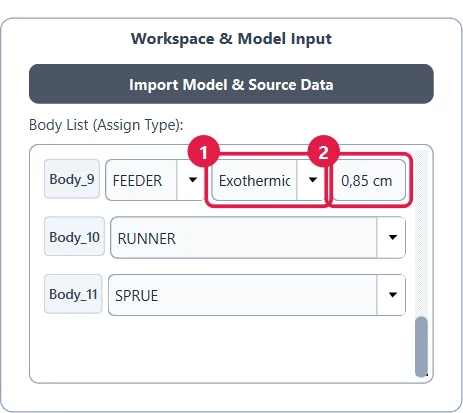
Feeders have two extra boxes: the feeder type (1) and the feeder modulus (2).
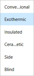
Feeder types: Conventional (plain sand feeder), Exothermic (sleeve that generates heat), Insulated (sleeve that keeps heat in), Ceramic/Magnetic, Side and Blind feeders.
For the sample: all three feeders are Exothermic; modulus 0.25 cm for Body_3 and Body_4, 0.85 cm for Body_9. (Use the value given by your sleeve supplier for your own parts.)
A CORE body also gets a sand-type box. For the sample, choose Silica Sand for Body_8.
Step 3 — Choose the alloy and the mould sand
In 1. Analysis Settings, choose the Alloy (1) and the Mould Sand Type (2).
For the sample: GGG60 (Ductile Cast Iron) and Green Sand.
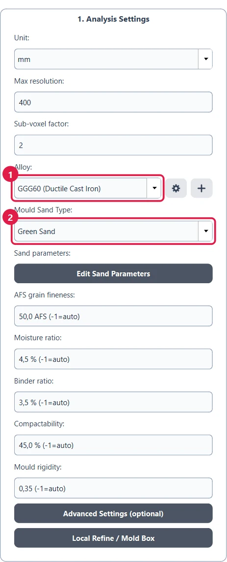
Leave the other fields (resolution, sand parameters …) at their default values for your first analyses. Max resolution 400 is a good balance between detail and run time.
Available alloys: carbon and cast steels (C35, C45, C60, GP240GH, G20Mn5), alloy steels (16MnCr5, 20MnCr5, 42CrMo4, 100Cr6), manganese steels, stainless steels (AISI 304, 316), ductile irons (GGG40/50/60, Ni-Resist), compacted graphite iron (GJV-450), grey irons (GJL200/250/300) and white irons (Ni-Hard 1/2/4).
Available sands: Green, Silica, Chromite, Zircon, Furan resin, Phenolic resin, Water glass and Shell (Croning).
Step 4 — Casting parameters
In 2. Casting Parameters:
- Pouring temperature (1) — the temperature of the metal entering the mould. It is filled in automatically from the alloy; change it to your real practice. Sample: 1390 °C.
- Velocity section (2) — where the program calculates the metal inlet speed. Choose the sprue option (automatic, from the sprue height). The program then calculates the speed itself.
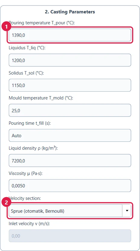
The other values (liquidus, solidus, density …) come from the alloy — leave them as they are. Pouring time on Auto lets the program calculate it.
Step 5 — Gravity direction (very important)
Choose the direction in which gravity acts on your model (1), i.e. which way is "down" in the mould. This depends on how the model was drawn in CAD.
For the sample: (-X). In the 3D view the sprue funnel must then point upwards.
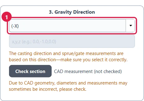
⚠ A wrong gravity direction gives a completely wrong result (the metal would "fall" sideways). If your CAD model is drawn with Z up, choose (-Z).
Click Check section to let the program measure the sprue and gate sections on the CAD model; check that the values look right.
Step 6 — Mould box
At the bottom of section 1, click Local Refine / Mold Box. A box appears around the model in the 3D view — this is the sand mould. A dialog lets you set how much sand surrounds the model in each direction (in mm).
For the sample: 0 mm on X+ (the top of the mould, where the sprue opens) and 30 mm on all other sides. Click OK.
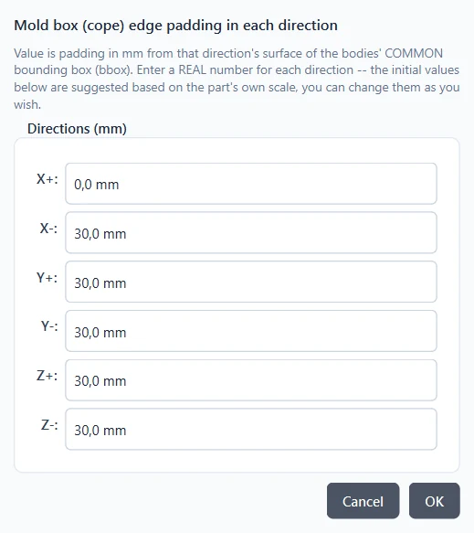
Why 0 on the top? The sprue and the open feeders must reach the top surface of the mould, as in a real flask.
Step 7 — Voxelize
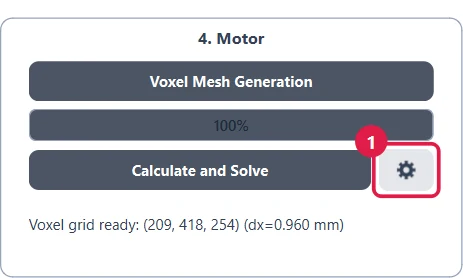
In 4. Motor, click Voxel Mesh Generation (1). The program converts the CAD model into a fine 3D grid of small cubes (voxels) that it can calculate on. This takes from a few seconds to a few minutes.
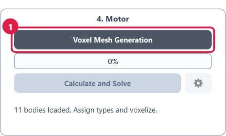
When the bar reaches 100 %, the bodies are shown in colour by type (part, feeders, runners, sprue) and the log shows the grid size.
Step 8 — (Optional) choose what to calculate
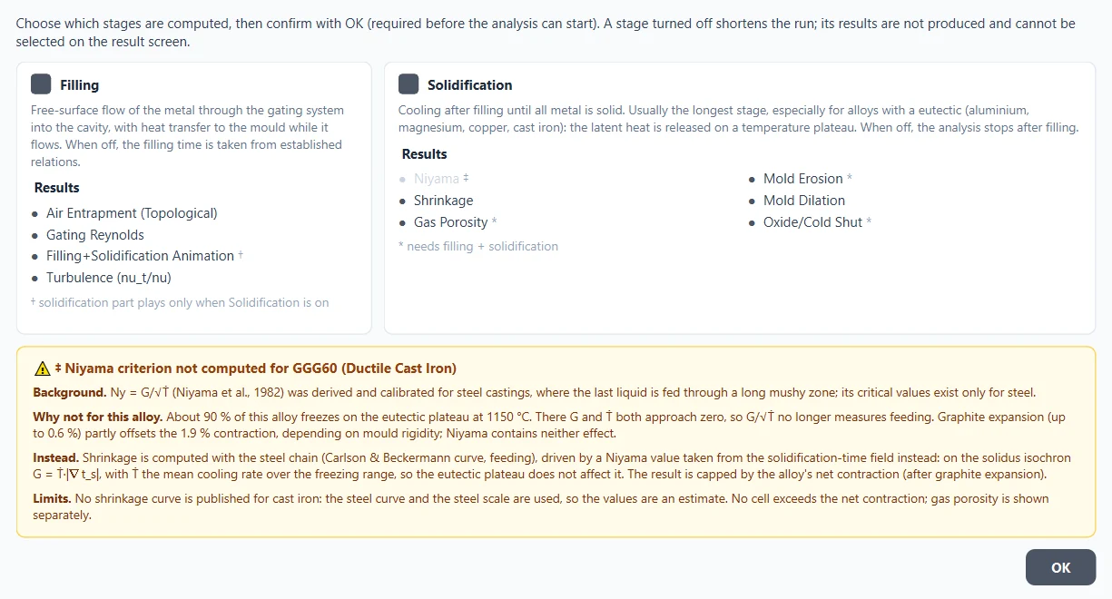
The gear button next to Calculate and Solve (1) opens Simulation Stages.
- Filling — the flow of the metal through the gating system into the mould.
- Solidification — the cooling and solidification after filling.
Each stage lists the results it produces. Keep both stages on for a complete analysis.
Filling off (quick check): If you only want to check feeding and shrinkage, switch Filling off. The program then does not simulate the flow: it estimates the filling time and the temperature of the metal at the end of filling, and starts solidification from there. The run is much shorter, but flow results (air entrapment, cold shuts, turbulence …) are not produced.
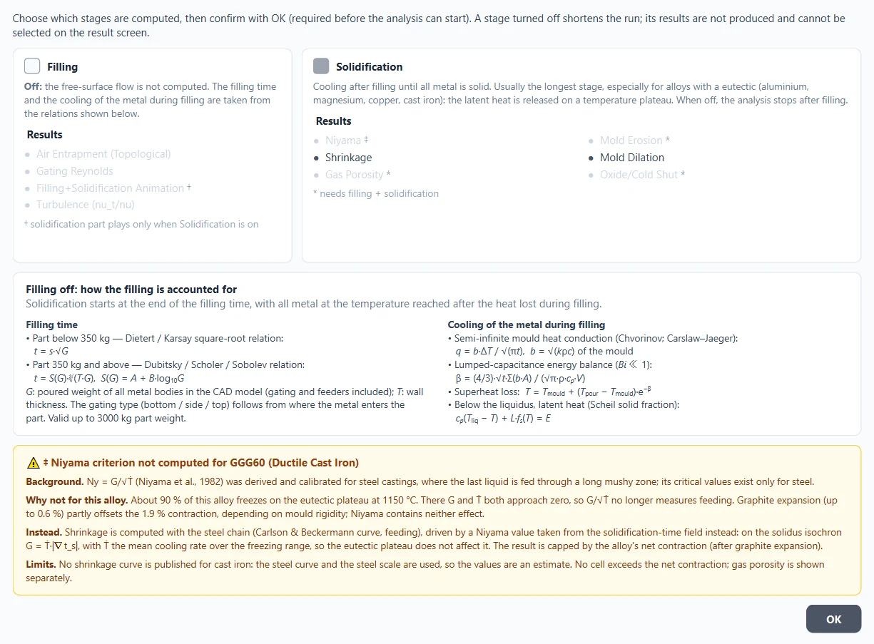
Click OK to confirm.
Step 9 — Calculate
Click Calculate and Solve (1).
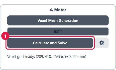
The progress bar shows the current stage (filling or solidification) and the percentage. The log keeps you informed. The same button becomes Stop while the analysis is running.
When the analysis is finished, the right panel opens and the result appears automatically.
4. Reading the results
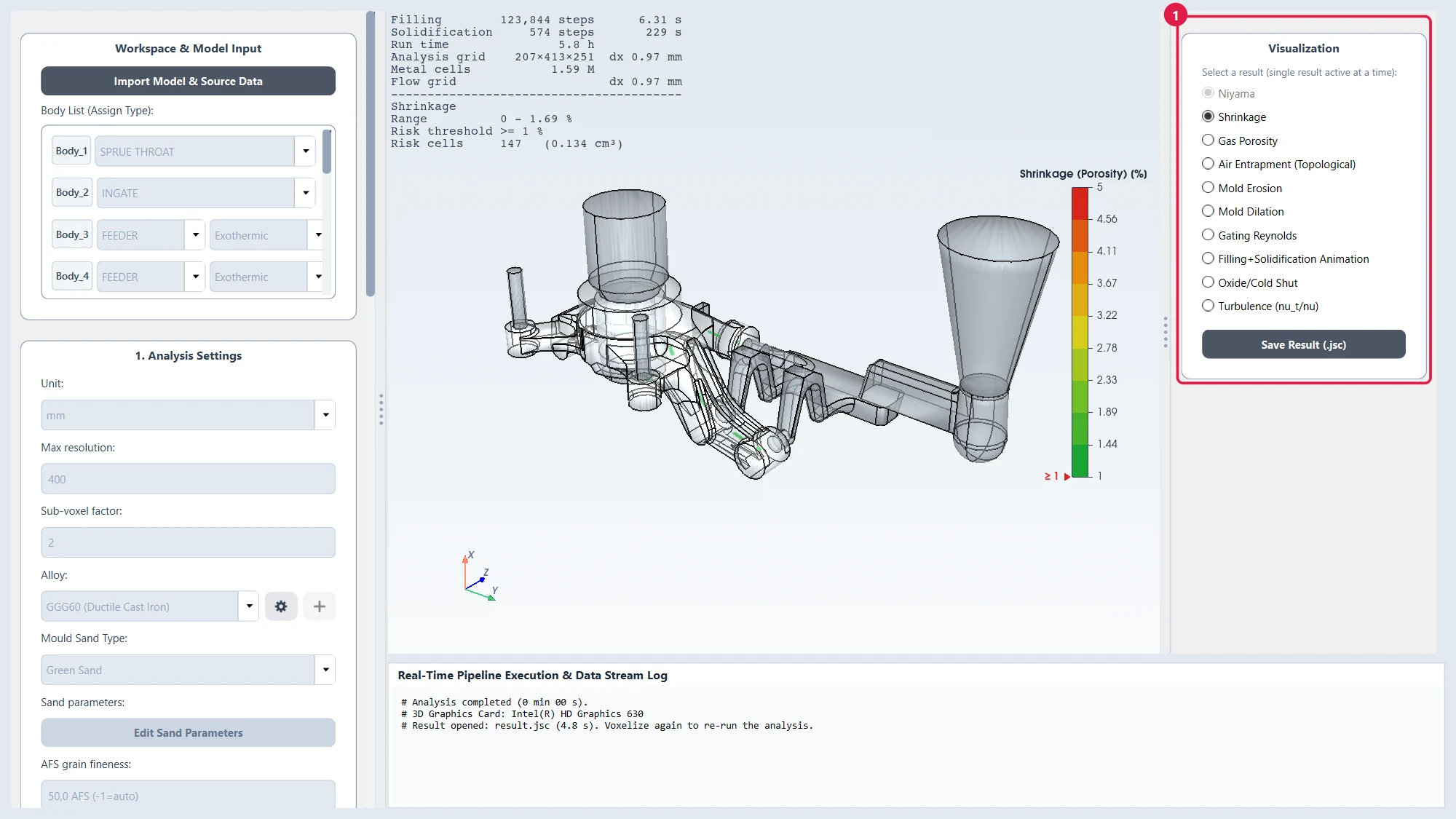
Choose a result in the Visualization list on the right (1). Only one result is shown at a time.
On every result screen:
- Top-left text — a summary of the run: filling time, solidification time, grid size, and for the selected result its range, its risk threshold and how many cells exceed the threshold.
- Colour bar (right) — the scale. The small red arrow and the "≥" value mark the risk threshold.
- 3D view — only the regions at or above the threshold are coloured; the rest of the casting is shown transparent so you can see inside.
- Bottom slider — move the threshold yourself to see weaker or only the strongest risks.
How to read colours: green = just above the threshold, yellow/orange = stronger, red = strongest. No colour = no risk at the threshold.
Shrinkage (porosity)
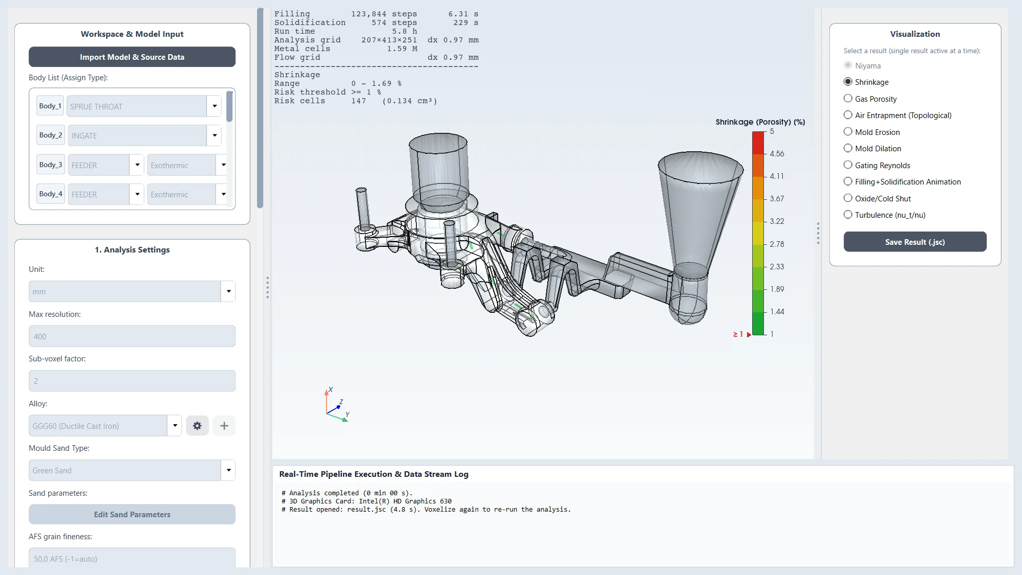
What it shows: where the metal shrinks during solidification and cannot be fed with liquid metal — the most common internal defect (shrinkage cavities and porosity).
What to do if you see risk inside the part: move or enlarge the feeder near that region, increase the feeder modulus, add a chill, or change the gating so the region solidifies earlier. Risk inside the feeders is good — that is where shrinkage should end up.
In the sample, risk is limited to a very small volume (147 cells, 0.134 cm³).
Gas porosity
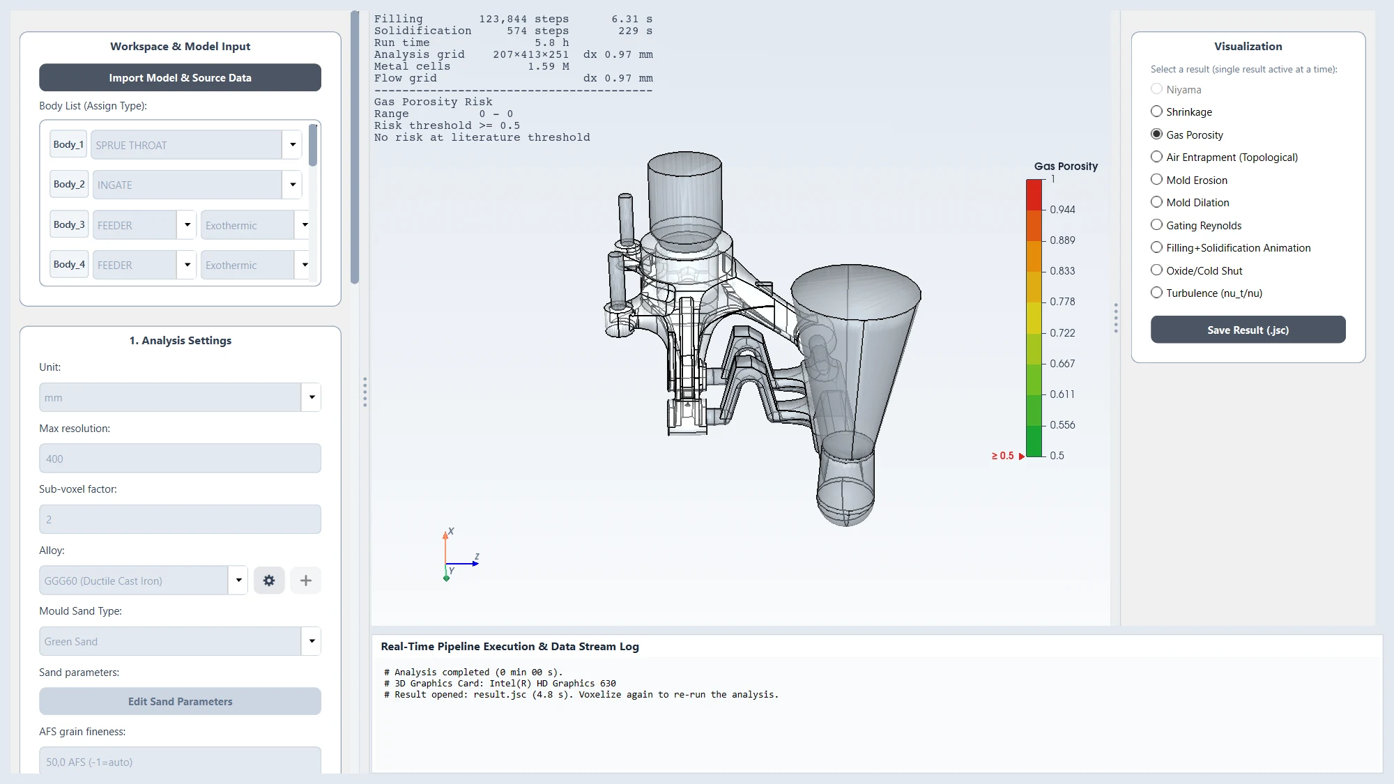
What it shows: where gas from the metal or the mould can form bubbles that the metal pressure cannot hold back. In the sample: no risk at the threshold.
What to do: better venting, lower sand moisture, a higher metallostatic head over the region.
Air entrapment
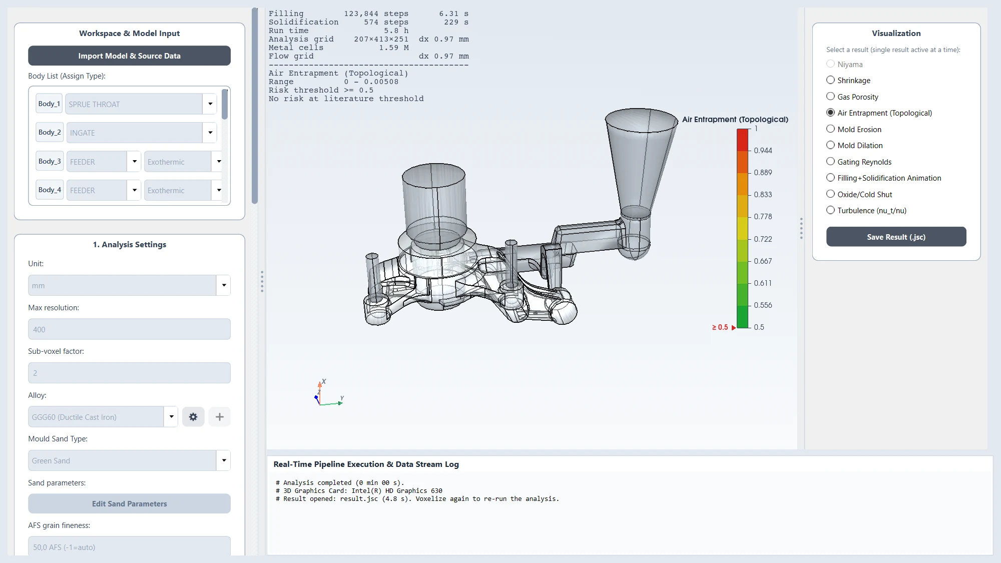
What it shows: pockets where the air in the mould is closed in by the rising metal and has no way to escape — they can leave blowholes or misruns.
What to do: add a vent or a feeder at the highest point of the pocket, or change the filling order with the gating.
Mould erosion
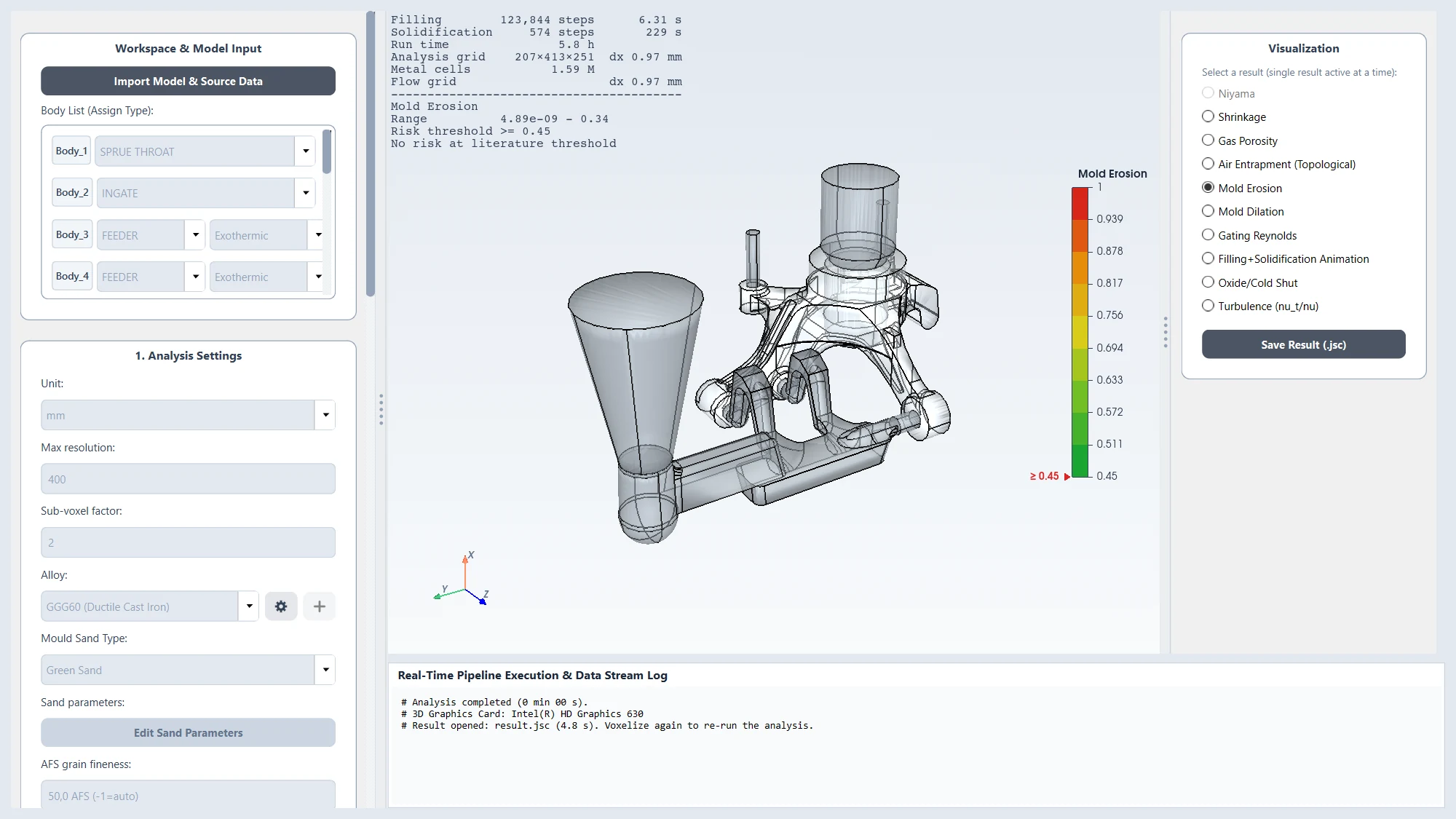
What it shows: where fast or impacting metal can wash sand off the mould wall — sand inclusions in the casting.
What to do: reduce the gate velocity (larger gates, a choke in the right place), avoid jets hitting mould walls or cores, use a harder sand/coating at that spot.
Mould dilation
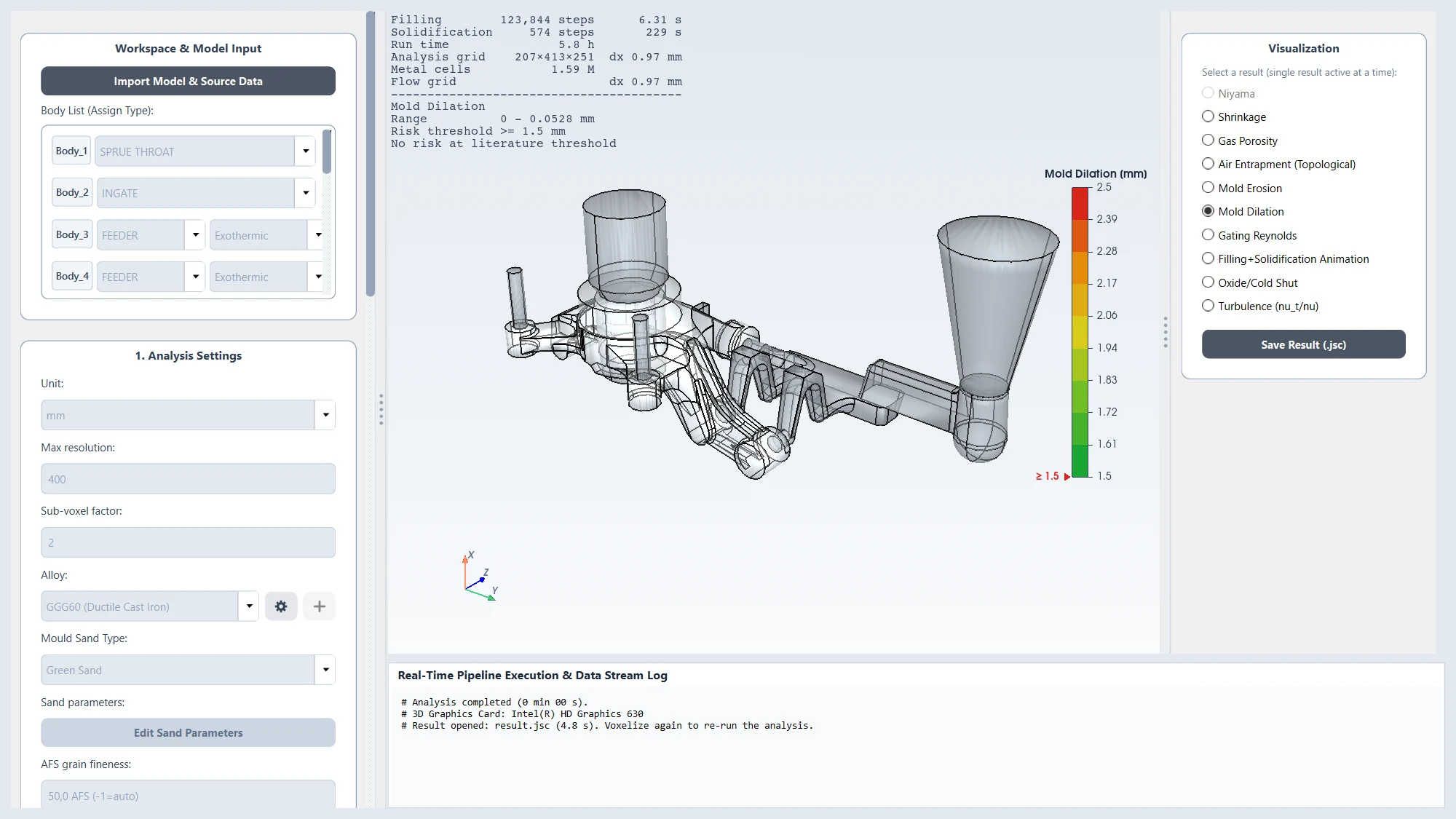
What it shows: how much the sand mould wall moves outward (in mm) under heat and metal pressure — oversize dimensions, swells and fins.
What to do: firmer mould (higher compaction, stronger binder), lower pouring height.
Gating Reynolds
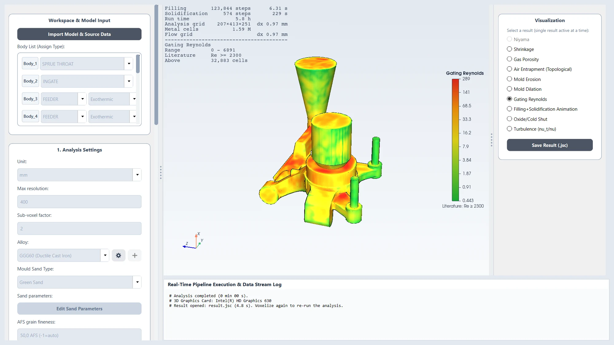
What it shows: how turbulent the flow is in each region (Reynolds number). High values in the gating system mean a violent, splashing flow that creates oxides.
What to do: a smoother, wider gating system; avoid sharp corners and sudden section changes.
Filling + solidification animation
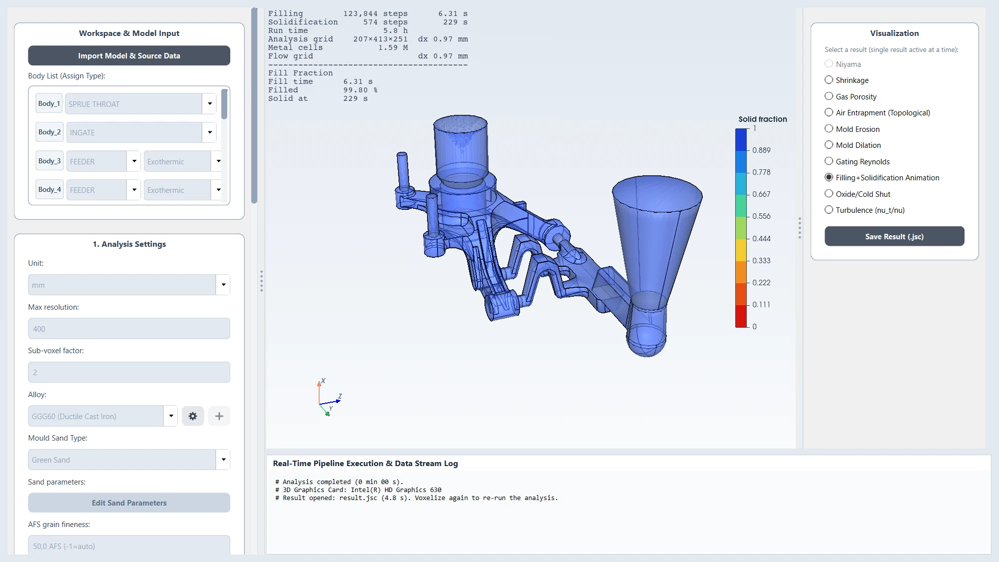
What it shows: a film of the whole process. Press play on the bottom bar: first the metal fills the mould (colour = flow speed), then the casting solidifies (colour = solid fraction). It is the best way to see the filling order and where the last liquid metal remains.
Oxide / cold shut
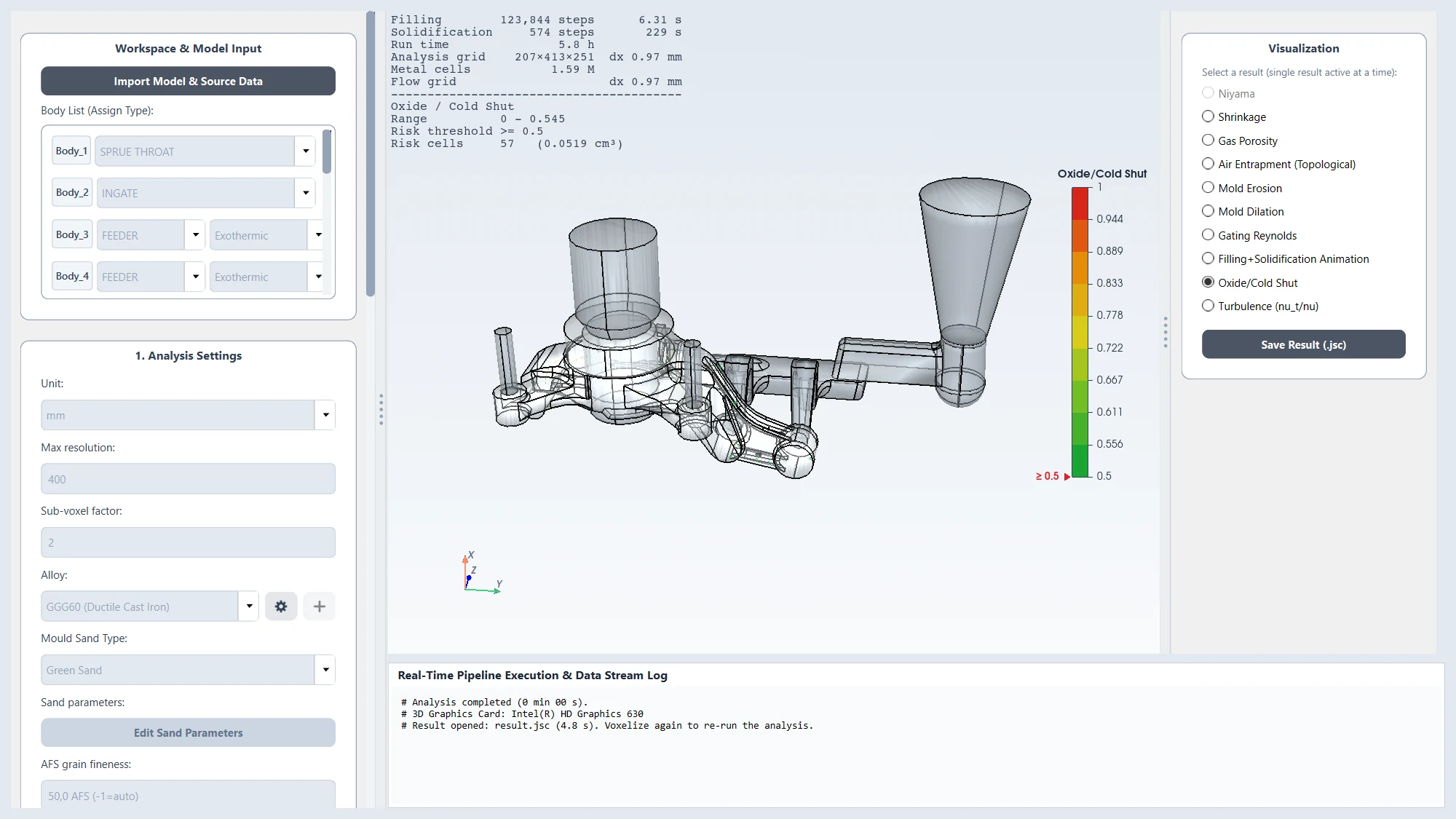
What it shows: places where two metal fronts meet after they have already cooled down — they may not fuse properly (cold shut, cold lap) or trap an oxide film.
What to do: higher pouring temperature, shorter filling time, an extra gate so the fronts meet earlier and hotter.
Turbulence
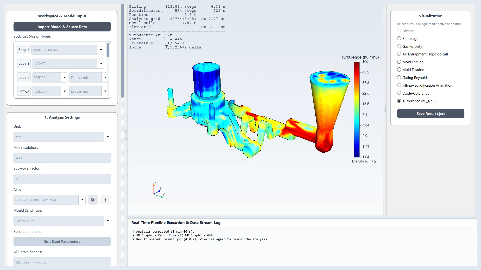
What it shows: how much stronger the flow mixing is than in calm flow. Strong turbulence folds the metal surface in and creates oxide inclusions. It is normally highest in the sprue and the runner — what matters is that it calms down before the metal enters the part.
Niyama appears in the list for steels. It is not shown for cast irons, because the classic Niyama criterion is not valid for them; for cast irons use Shrinkage.
5. Saving and opening results
Every finished analysis is saved automatically in Documents\JoseCast Analyzer\Jobs\<date>_<time>_<model name>\result.jsc.
To save a copy elsewhere (for example to send to a colleague), click Save Result (.jsc) (1).
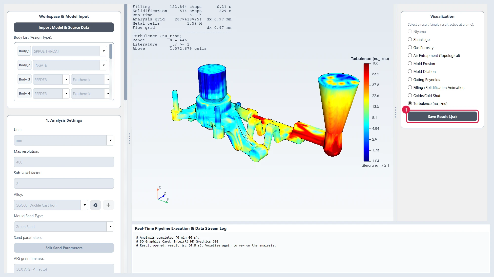
To open a result later: click Import Model & Source Data and choose the .jsc file. All results are available again immediately — no recalculation needed.
Job folders can be large (up to a few GB). You can delete old job folders inDocuments\JoseCast Analyzer\Jobswhen you no longer need them; save the.jscfirst if you want to keep the result.
6. Long runs: closing the program while it calculates
The calculation runs in its own separate process. If you close the window during an analysis, the program asks:
- Keep Running and Close — the window closes, the calculation continues in the background and writes its result.
- Stop Solver and Close — the calculation is stopped; this run gives no result.
When you open JoseCast Analyzer again:
- if the analysis is still running, the program offers to reconnect and show its progress;
- if it finished while the program was closed, it offers to open the result.
Do not shut down or restart the computer while an analysis is running in the background.
7. Preparing your own model
- Model the complete casting system in your CAD program: part, feeders, sprue, runners, gates (and cores, if any).
- Every component must be a separate solid body. Bodies may touch each other.
- Export as STEP (
.stp/.step). - Note which axis points up in your CAD model — you will need it for the gravity direction.
- Import, then follow steps 2–9 exactly as with the sample.
Good practice
- Start with the default resolution (400). Increase it only for very thin walls.
- Always check the gravity direction in the 3D view: the sprue must point up.
- Give the feeder modulus and type of the sleeves you really use.
- Use Filling off for quick feeding checks while you design; run the full analysis for the final layout.
8. Scope and limits
- Process: gravity casting in sand moulds.
- Alloys: steels (carbon, cast, alloy, manganese, stainless) and cast irons (ductile, compacted graphite, grey, white). Aluminium, magnesium and copper alloys are not included.
- Results are predictions to support your decisions. They show where and how likely a defect is, so you can improve the design before production. Always confirm critical parts with your own experience and inspection.
9. Quick troubleshooting
| Problem | Solution |
|---|---|
| Calculate and Solve stays grey | Run Voxel Mesh Generation first. |
| The metal seems to flow sideways or upward | Wrong gravity direction — check step 5. |
| The model has only one body | The STEP file was exported as one merged solid. Export each component as a separate body. |
| The run takes very long | Lower Max resolution, or use Filling off for a first feeding check. |
| A result button is grey | That result was not calculated (stage switched off) or does not apply to the chosen alloy. |
| The program was closed during an analysis | Open it again — it offers to reconnect or to open the finished result. |
JoseCast Analyzer — josecastsuite.com